Final Report
1 INTRODUCTION
This research has been motivated by the humble and pure minds of Team AF in pursuit of the truth and knowledge to make the world and tomorrow better. Pedestrians, when crossing the street, need to be vigilant (using both eyesight and hearing), which is not inclusive towards elderly pedestrians or blind or deaf pedestrians. Pedestrian signals are always on even when pedestrians are not in the vicinity, which is a waste of energy. In an effort to reduce energy costs and make crossing streets easier for disabled or elderly pedestrians, we aim to improve pedestrian crossing lights by developing a new data acquisition system that will detect motion, sound, and light and transmit information to the pedestrian light.
2 PROBLEM STATEMENT
The aim of this project is to create an assistive sensor-based pedestrian signal that utilizes a combination of sound, PIR, photosensitive and vibration sensors to detect pedestrian motion and sounds and also passing cars so that the pedestrian signal gives the appropriate signal to either cross the road or wait. During times when no pedestrians are detected, the signal is off in order to save energy.
3 REVIEW OF SENSORS BEING UTILIZED
3.1 Sound Detection Sensor Module
3.1.1 Physical Principles
The Sound Detection sensor module has a built-in capacitive electret microphone which is highly sensitive to sound. Sound waves cause the thin film of the electret to vibrate and then the capacitance changes, thus producing the corresponding changed voltage, so it can detect the sound intensity in ambient environment. Since the change is extremely weak, it needs to be amplified. We use a LM393 as the power amplifier here. You can adjust the sensitivity by adjusting the Potentiometer. When the sound level exceeds the set point, an LED on the sensor module is illuminated and the output is sent low. Note: This sound sensor is used to detect whether there’s sound surround or not; it cannot recognize the frequency or volume.
3.1.2 Sensor Characteristics
Specifications of sound detection sensor module:
- Working voltage: DC 3.3-5V
- Adjustable Sensitivity
- Dimensions: 32 x 17 mm
Output in the form of digital switching outputs (0 and 1 high and low)
The image and table below detail the controls, pin outs, and other key components.

Figure 1. Sound sensor module
GND, is connected to ground, then VCC is connected to +5V
On the top of the sound sensor is a little flathead screw you can turn to adjust the sensitivity and analog output of the sound sensor. To calibrate the sound sensor you can make some noise and keep turning it until you start seeing the sensor-LED on the module starts blinking with the rhythm. When less sensitive, it takes more sound to trigger the device. When more sensitive, it takes less sound to trigger the device.
3.1.3 Applicability
- Security system for Office or Home
- Home Automation
- Smart Phones
- Audio amplifier
3.2 HC-SR501 Infrared PIR Motion Sensor Module
3.2.1 Physical Principles
Infrared radiation (IR) corresponds to one of the ways in which heat is transferred from one place to another. The IR fluctuations for detecting motion are widely used since all objects on earth emit IR (or heat). These fluctuations are measured through passive infrared sensors, which capture variations depending on several aspects, including: (1) the distance of the body from the PIR sensor, (2) the direction and speed of movement, and (3) the body shape and gait. These sensors are well-known occupancy detectors due to their low cost, low power consumption and small form factor. Here, we are using a PIR motion sensor. PIR stands for Passive InfraRed. This motion sensor consists of a fresnel lens, an infrared detector, and supporting detection circuitry. The lens on the sensor focuses any infrared radiation present around it towards the infrared detector. Our bodies generate infrared heat and as a result, this gets picked up by the motion sensor. It can be said, the more heat emitted by a body, the more is it prone to be detected by the sensor.

Figure 2. PIR motion detection principle 1
When an object, such as a human, passes in front of the background, such as a wall, the temperature at that point in the sensor’s field of view will rise from room temperature to body temperature, and then back again. The sensor converts the resulting change in the incoming infrared radiation into a change in the output voltage, and this triggers the detection. Moving objects of similar temperature to the background but different surface characteristics may also have a different infrared emission pattern, and thus sometimes trigger the detector.
PIR Sensing Angle diagram:

Figure 3. PIR motion detection principle 2
3.2.2 Static and Dynamic Behavior
Static behavior: This sensor works with the change of amount of infrared emitted from the environment. Upon that, static behavior means when the amount of heat (infrared) received by the sensor is constant. In this occasion, the PIR sensor doesn’t detect anything.
Dynamic Behavior: When the amount of infrared received by the sensor changes, either by physical motion or heat generation by operation of an instrument, the PIR sensor can detect the phenomenon.
3.2.3 Sensor Characteristics
Specifications of HC-SR501 Infrared PIR Motion Sensor Module:
- Working voltage: 4.5V to 20V
- Output: High: 3.3V, Low: 0V
- Detection angle: Approximately 120 degrees
- Range: Adjustable, up to 7m
- Dwell time: (Stay-ON time) adjustable between 5-300 Seconds. –– it can be further increased by increasing the value of the CY1-Timing capacitor on pin 4 of the IC
- Operating Temperature: -20 – +80 Degrees C.
- PCB Dimensions: 33x25mm, 14mm High not including the Lens; Lens: 11mm high, 23mmDiameter.
- Weight: 6g
- Communication: Single Bit Input/Output
- Detect a person up to ~30 ft. away, or up to 15 ft
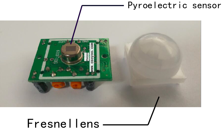
Figure 4. HC-SR501 PIR motion detector
PIRs are basically made of a pyroelectric sensor (which you can see above as the round metal can with a rectangular crystal in the center), which can detect levels of infrared radiation. The sensor in a motion detector is actually split in two halves. The reason for that is that we are looking to detect motion (change) not average IR levels. The two halves are wired up so that they cancel each other out. If one half sees more or less IR radiation than the other, the output will swing high or low. This sensor is then placed behind a multifaceted lens (a Fresnel lens) that “chops up” the view of the world into smaller cones of heightened visibility and intervening areas of lessened visibility thus widening the useful viewing /detection angle dramatically. The PIR sensor itself is housed in a hermetically sealed metal can to improve noise/temperature/humidity immunity. There is a window made of IR-transmissive material (typically coated silicon since that is very easy to come by) that protects the sensing element.
As mentioned, the adjustable range is from approximately 3 to 7 meters. The illustration below shows this adjustment.
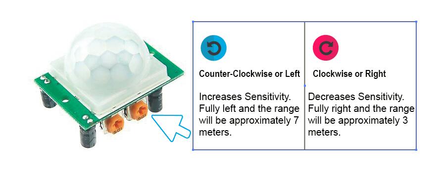
Figure 5. HC-SR501 PIR motion detector; sensitivity adjustment
The time delay adjustment determines how long the output of the PIR sensor module will remain high after detection motion. The range is from about 5 seconds to five minutes. The illustration below shows this adjustment.
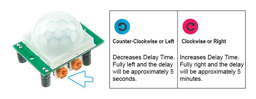
Figure 6. HC-SR501 PIR motion detector; delay-time adjustment
The output of this device will go LOW (or Off) for approximately 5 seconds after the time delay completes. In other words, all motion detection is blocked during this three second period.
3.2.4 Applicability
- Build burglar alarm systems
- Home automation systems
- Occupancy Detection
3.3 Photosensitive Light Sensor Module
3.3.1 Physical Principles
Presence/absence of light: To measure presence or absence of light, the principle of photo-resistance/photo-conductance is applied. When light is incident on a photo-resistor the electrons are excited in the semiconductor and move to the conduction band. This reduces the resistance of the photo-resistor and allows a current to flow through it. The current flowing through the sensor is proportional to the intensity of light incident upon it and is also a function of the temperature of the sensor. The temperature of the sensor increases with prolonged exposure to light. In complete darkness, the electrons lose energy and leave the conduction band. This causes the resistance of the sensor to increase preventing current from flowing through it. To detect the presence or absence of light we need to measure the magnitude of current flowing through a circuit with a photo-resistor.
3.3.2 Sensor Characteristics

Figure 7. Photosensitive sensor module
The output is in digital and tells us only whether light is present or not and not its intensity or brightness. When the photoresistor is covered, the signal is LOW indicating absence of light and when it is uncovered and exposed to light, the signal is HIGH.
3.3.3 Applicability
- Streetlights
- Alarm devices
- Night lights
3.4 Vibration Sensor Module
3.4.1 Sensor Characteristics
Specifications:
- Operating voltage 3.3V-5V
- The output in the form: Digital switching outputs (0 and 1)
- A fixed bolt hole for easy installation
- Small board PCB size: 3.2cm x 1.4cm
- Wide voltage LM393 comparator
This Vibration Sensor can be used to detect vibration from any angle. There is an on-board potentiometer to adjust the threshold of vibration. It outputs logic HIGH when this module not triggered while logic Low when triggered.
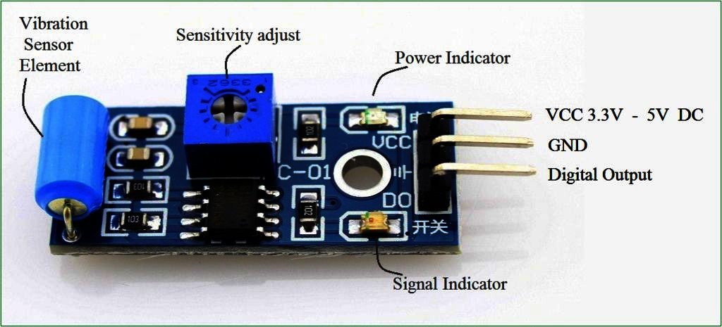
Figure 8. Vibration sensor module
3.4.2 Applicability
- Automobile alarm
- Movement detection
4 LOGIC + BLOCK DIAGRAM EXPLAINED
The block diagram below shows the high level logic that we developed in order to optimally implement our project. Our code essentially starts by checking if there is a person or not based on the binary signals detected by the sound and motion sensors. If there is no person, then the entire pedestrian signal is turned off. If there is a person detected, then the traffic signal checks if there is a car detected based on the binary signals from the vibration and motion sensors. If there is a car then the pedestrian signal turns red. We interpret the existence of a car as being the existence of a moving car since we are detecting motion. Thus, no matter what the traffic signal phase is, the pedestrian should not cross the street since a moving car is detected. This portion of our logic is novel to traffic systems in general because it is situationally dynamic and therefore proves that our system is not just based on a temporally dictated traffic signal.
Moving forward in the block diagram, if no car is detected, then the traffic signal phase is checked. If the traffic signal is green or yellow, then the pedestrian signal is turned red. If the traffic signal is red, then the amount of time left in the traffic signal phase is checked. If there is enough time left in the phase for a pedestrian to cross the street (some empirically determined threshold time value), then the pedestrian light is turned green. Otherwise, the pedestrian light is turned red and the pedestrian must wait until the next phase to cross the street. As such, our system only allows for one condition where the pedestrian signal is turned green after multiple decisions are made about the system. In this way, we are maximizing the safety of the pedestrian using layers of conditions in this block diagram.

Figure 9. Block diagram of Assistive Sensor-Based Pedestrian Signal
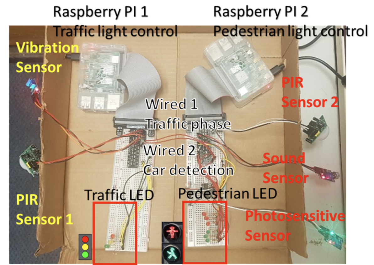
Figure 10. Demonstrative implementation of Assistive Sensor-Based Pedestrian Signal
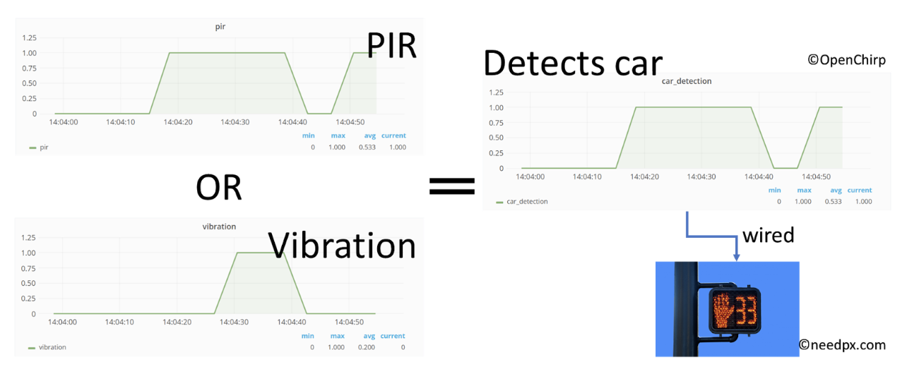
Figure 11. Car detection algorithm; if either PIR sensor or vibration module detects rushing car from the post, car detection information is transferred to prevent the pedestrian signal from being turned on. The signal images are generated from OpenChirp while the pedestrian signal. Image was downloaded from ‘needpx.com’.
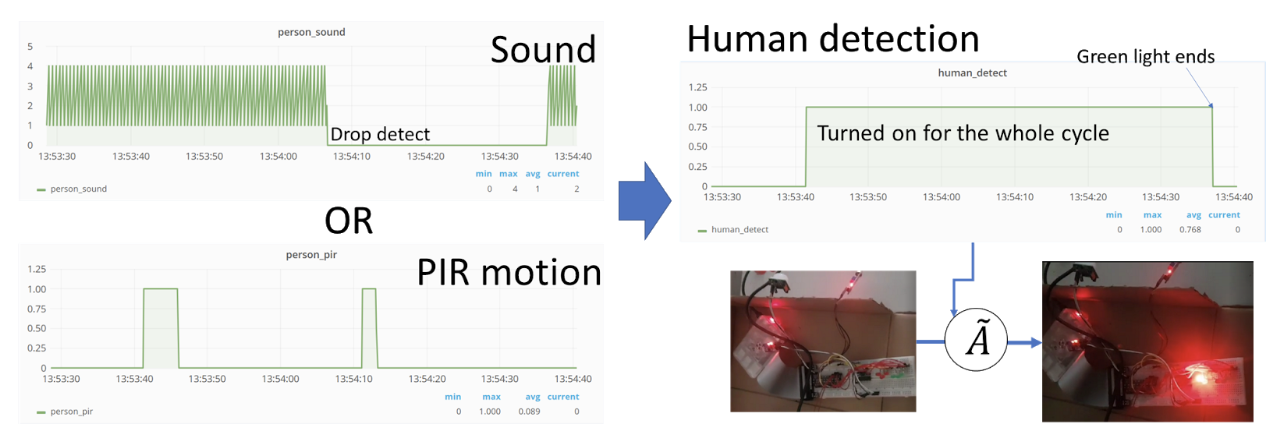
Figure 12. Human detection algorithm; if there is either PIR motion detection or sound, pedestrian signal detects the existence of humans so that the light is turned on and will be off after people cross the walk. This feature of the traffic signal enables to save energy while assisting people who need more care to cross the street.
5 EXPERIMENTS
The iterative nature of the engineering design process was definitely emphasized during this project. This is clear from all of the posts included in the rest of this webpage. Although we did largely achieve what we set out to accomplish, the way in which we accomplished our goal was very different from the way we would have predicted it to happen. More accurately, when we started the project we had no idea how we were going to achieve our end goal. On a high level, we experienced three major iterations, each iteration having its own smaller iterations.
During the first iteration, we worked towards understanding the sensors from a hardware perspective. We ensured that each sensor was working on its own, meaning that we had to connect each sensor individually and test each respective sensor. It was during this iteration that a lot of the high level understanding of how the real world fit in with our project since this was not excessively clear at the start. Although we did understand largely that we were building a smart pedestrian signal for elderly and disabled pedestrians, it was difficult to really have an understanding of what the device could do without thoroughly understanding what each sensor does and how data is acquired from each sensor. Thus, it was during this iteration that we understood that all of our sensors send binary data except for the photosensitive sensor. Upon understanding this information, we were able to generate a trajectory for how to use this data optimally in order to reach our end goal. After connecting each sensor individually, we were able to slowly build one functioning circuit that incorporated all sensors needed. This process was very slow since we quite literally were connecting one sensor at a time. Although this process was excruciatingly slow, it allowed us to really develop an understanding of the hardware and the Python scripting needed to acquire data from each sensor.
During the second iteration, we were able to build some logic on top of our existing system. This meant making LEDs light up under varying conditions. This particular iteration took a lot of effort as well because LEDs are very finicky. The hardest part about this iteration was getting the LEDs to come on exactly when we wanted them to. Sometimes LEDs would be flickering, sometimes they wouldn’t come on at all, and other times they would just stay on all of the time without following any of the conditions we set. Even after we figured out how to reliably turn LEDs on and off according to some logical conditions in our code, our problem was time delay. Sometimes our time delay was so high that the LED would come on exactly when it wasn’t supposed to come on. It was during this iteration that we realized the importance of accuracy in our system. This would play a role in the third and final set of iterations in this project. Regardless, by the end of this iteration, we were able to turn an LED on when the traffic light was red and off when the traffic light was green. In addition, the LED turned off when there was no pedestrian. This all happened with a significant time delay, meaning that the system only worked effectively approximately 70% of the time.
During the third and final iteration, we worked mainly on robustness and accuracy which cooperatively equate to safety. Throughout this project, safety really grew to be our #1 priority. For this reason, we felt motivated to eliminate the time delay in our system as much as possible. This necessitated a more robust way to read in the LED on/off signals since many times, for whatever reason, the system was receiving an unreliable or fake signal from the LEDs. To mitigate this problem, we used a very basic averaging method to only take a signal from the LED if it was happening over and over throughout a fairly long period of time (our phasing was approximately 30 seconds per light); we call this filtering method a primitive filter. Figures 5-7 represent the working process of this filter. This primitive filter reduced our error drastically but not completely. In addition, during this iteration we implemented a more sophisticated form of our system that reflected the way the traffic signal and pedestrian exist on the road. Instead of having all sensors in one circuit, we split up all of the sensors relating to the traffic signal and all of the sensors relating to the pedestrian signal. In this way, it became easier to think about just the traffic signal as a subsystem that works at detecting cars, controlling the traffic signal regularly, and sending that data to the pedestrian signal subsystem. The pedestrian signal works at detecting pedestrians, collecting the data from the traffic signal subsystem in a timely manner, and controlling the pedestrian signal in a maximally safe way.
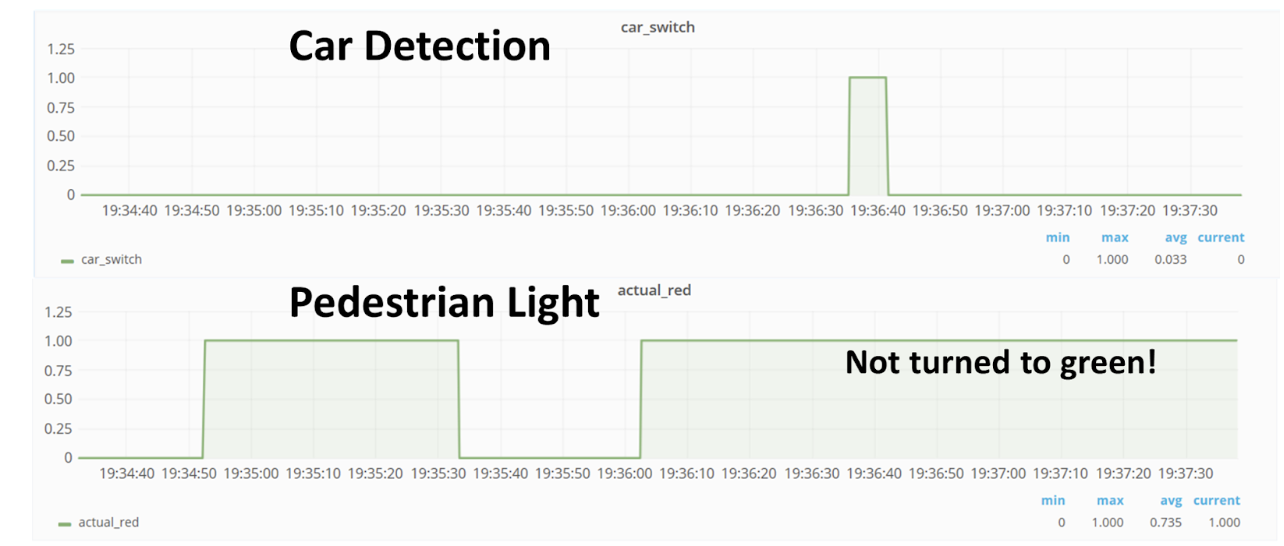
Figure 13. Car detection actuation. The pedestrian signal will not be turned to green if the traffic sensors detect rushing cars to maximize pedestrian’s safety.
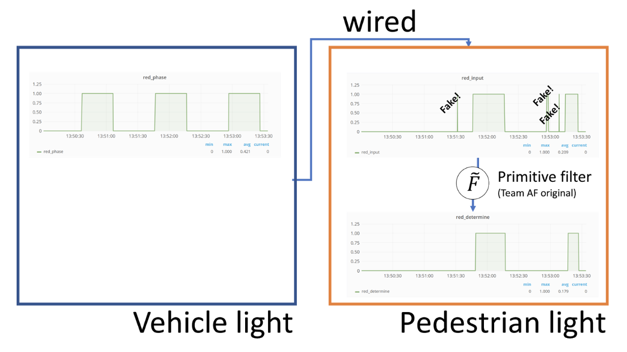
Figure 14. Sequential block in phase signal process. The vehicle light generates traffic phase following its inherently stored traffic schedule while the pedestrian light receives these values as input to control its lighting system. As shown in the figure, raw data from vehicle light implicitly includes undesired fake signals which hinder accurate control on pedestrian light system. The primitive filter provides a way to remove those unwanted signal with simple logics.

Figure 15. Diagram of Primitive Filter. To determine the actual status of the input signal, the Primitive Filter is constituted by two components of signal; one is to activate the signal while the other is to inactivate it. Among the mixed True/False input values, the signal becomes HIGH if the activating values are accumulated enough to exceed a certain threshold while the signal becomes LOW if the inactivating values are accumulated enough to exceed their threshold. Since there is a discrepancy in their actuation reliability, the thresholds were set independently depending on their reliability. In our case, inactivation was more reliable than activation so that the delay to turn on green light is much longer than that of red light; since the red phase represents the red light for vehicles, the pedestrian light is green at those phase.
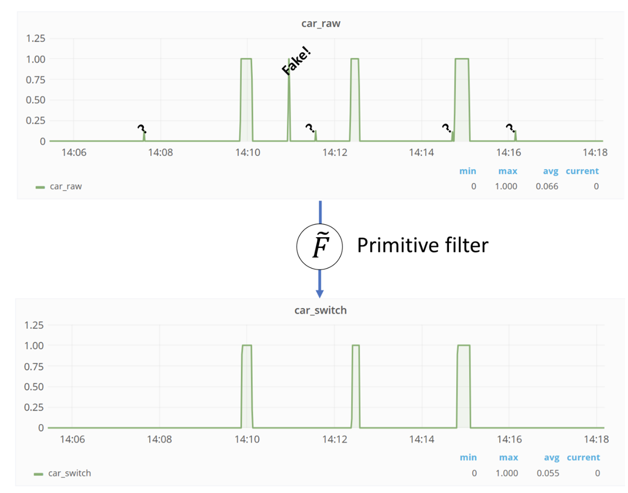
Figure 16. Sequential block in car detection signal process. Similarly with the phase process, the Primitive Filter has been applied to the car detection signal from the vehicle light.
On top of all of this, we added a lot of smaller details such as making the pedestrian light change brightness depending on the voltage read in by the photosensitive signal. We introduced the concept of making the pedestrian light blink when it is becoming closer to the end of the green phase for the pedestrian light. In addition, we introduced logic into the system that ensured the safety of the pedestrian by only turning the pedestrian light green if there is enough time left in the traffic light phase for the pedestrian to cross the street. Finally, we were able to read photosensitive data into OpenChirp, which was an iterative process in and of itself.
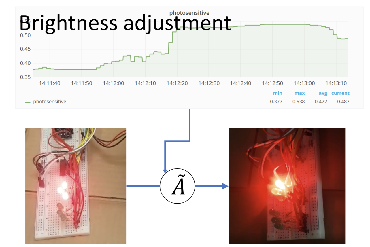
Figure 17. Brightness adjustment with photo-sensitive sensor. To maximize the energy saving in the transportation system, the daylight data collected from the photo-senstive sensor were used to adjust the brightness of the traffic light. In the figure, only one LED light is activated when it becomes dim.
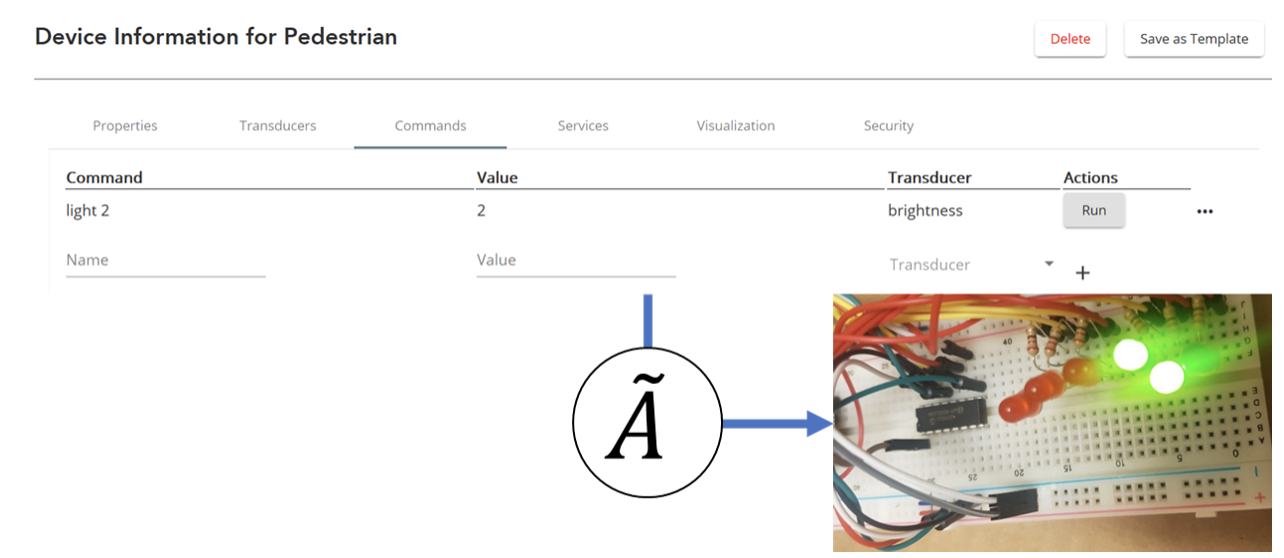
Figure 18. IoT based traffic signal control. The Assistive Pedestrian Signal was linked with OpenChirp. As an exemplary demonstration, we adjusted the number of LED light assuming the case when the signal is manipulated by the main control center.
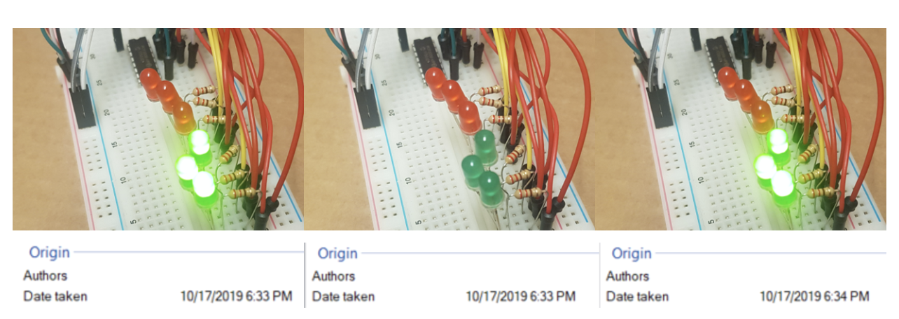
Figure 19. Blinking function of Assistive Pedestrian Signal. We implemented the blinkering to assist pedestrians to roughly know remained crossing-time.
6 APPLICATIONS
While building this smart pedestrian signal, we envisioned a scenario where a disabled or elderly pedestrian is at or approaching an intersection that is largely not crowded. In that specific situation, we believe that the intersection traffic light will not be excessively high tech. These intersections where there isn’t much traffic and there are definitely not many pedestrians end up being very different from intersections like Forbes and Morewood where there is a lot of traffic almost constantly and there are a lot of pedestrians crossing. As a result, there is an entire phase in the traffic signal at Forbes and Morewood dedicated to the pedestrians. In addition, at an intersection like Forbes and Morewood, it is important that that pedestrian scramble always be happening, no matter what time of day it is, because there will always be students wanting to cross that street. In a less crowded situation we do not see the need for the pedestrian signal to always be on since there are few pedestrians crossing ever. The current response to that situation is for the city to refrain from placing pedestrian signal buttons for pedestrians to press when about to cross the street or even to refrain from having pedestrian signals altogether. We find this to be unsustainable in the sense that at some point there will be pedestrians crossing the street, and at that point in time we want to always prioritize that pedestrian. It could be extremely dangerous for the pedestrian to be crossing without a button or without a signal altogether, especially if the pedestrian is elderly or disabled. Thus, we believe that our device would be most relevant to mitigate this problem for a sparsely populated intersection. At times where the signal is no longer needed, it would turn off completely as a sustainable measure. Otherwise, it would be able to detect a person based on sound and motion while protecting maximally from cars both following the law and not following the law.
7 FUTURE WORK
We have a wide variety of ideas that we would implement given the chance to continue working on this project. First of all, it was fairly upsetting to realize that the majority of our sensors only gave binary values. Some of our original ideas incorporated using thresholds on the continuous values to detect car and pedestrian movement or presence. Given the chance to keep working on this project, we would want to find more numerically robust sensors that give us more than just binary values. Aside from that, most of our sensors operated up to par, giving us reasonable sensitivity to external stimuli, except for the vibration sensor. The vibration sensor specifically lacked sensitivity severely. In order to implement this project better in the future we would want to obtain a more sensitive and more accurate vibration sensor in order to use thresholding to detect pedestrians and vehicles with one vibration sensor. Of course, the most important thing in our system is safety so we would want to continue to reduce the error so it approaches zero. The filtering scheme that we have implemented currently is extremely rudimentary, so we would want to really understand the best way to ensure that the signal being sent to the pedestrian light from the traffic light is 100% accurate in order to ensure that the pedestrian light is coming on exactly at the time when the pedestrian needs to cross the street.
Finally, we would want to improve the prototype itself in a multitude of ways. The organization of the hardware is not very sophisticated given that all we had to build this project was small LEDs and jumper wires. In the future we would want to make this device more compact and organized so as to mimic an actual pedestrian and traffic signal better. In addition, we found especially towards the end that we never really did any research on the technology behind traffic signals themselves. In the future, it would be helpful to really understand the current state of traffic signals from a hardware perspective in order to optimize our own system and make sure it works by the governmental standards in place.
References:
- http://kookye.com/2018/11/06/arduino-lesson-sound-detection-sensor/
- http://kookye.com/2018/11/06/arduino-lesson-pir-motion-sensor/
- https://en.wikipedia.org/wiki/Photoresistor
- http://wiki.marioberges.com/courses/12-740/index.php?title=Main_Page
- (Note: Some information was also collected from the past projects of students who took the Data Acquisition course.)
- http://kookye.com/2018/11/16/arduino-lesson-water-sensor-2/