Progress Report 6
We met today with the following goals:
- Test our system on its own with adjusted brightness
- Create a toy example to integrate part of our circuit into OpenChirp
- Integrate our entire circuit with OpenChirp
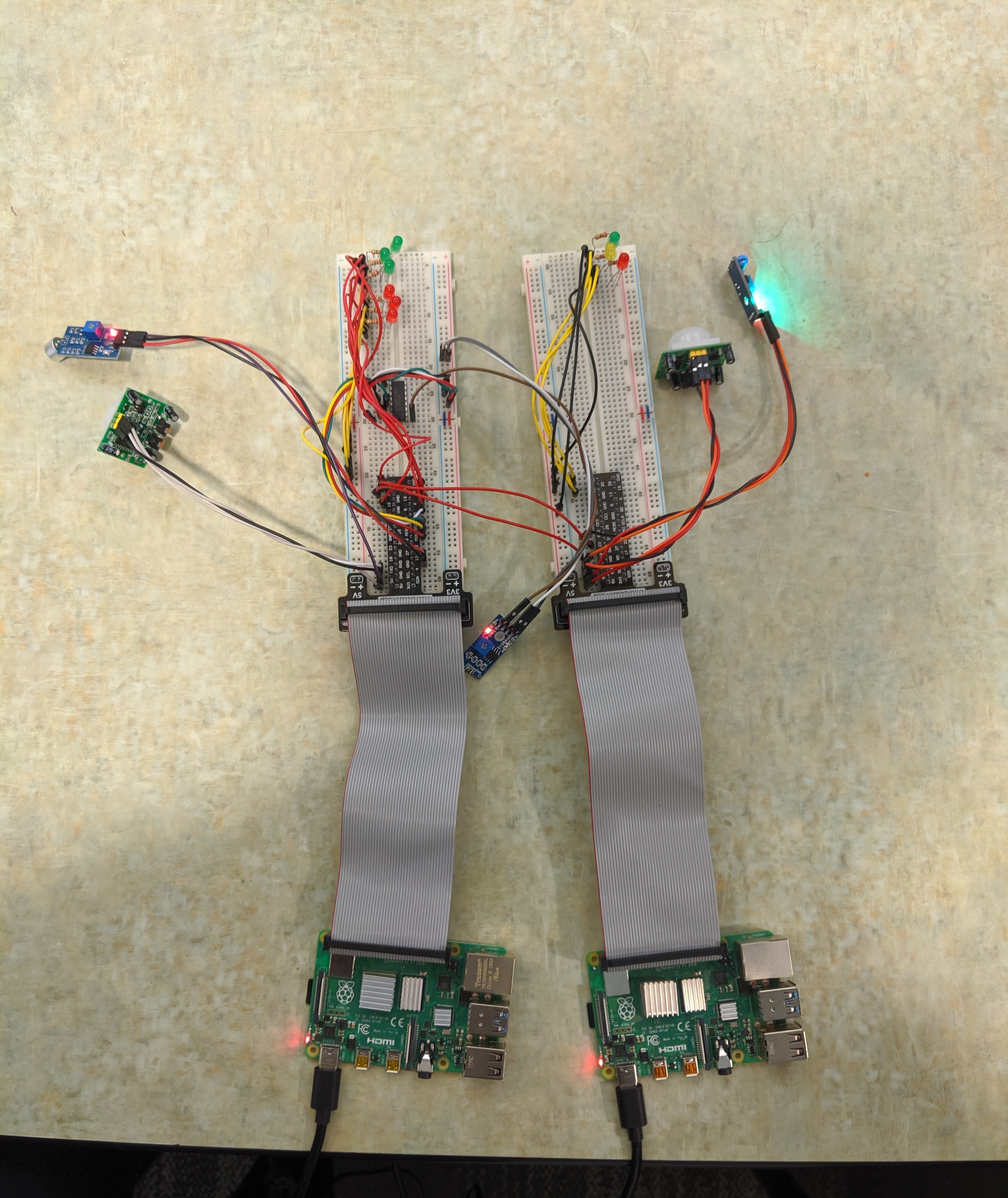
The image below shows the final iteration of our system. The Raspberry Pi on the left controls the pedestrian signal subsystem and the Raspberry Pi on the right is connected to the traffic light subsystem. Here, the new implementation of “brightness” of the pedestrian signal can be seen more clearly because of the three red LEDs and three green LEDs. The connection between the two is also clear here.

It took us several hours to understand how Mosquitto, OpenSSL, and OpenChirp work together to transmit data from our device to the OpenChirp interface. This involved understanding especially how the tokens and user ID worked in addition to the certificates required to permit the data transmission. At first we were only able to use the OpenChirp interface for just the light, as was done in the tutorial. Ultimately, we were able to integrate our working code from controlling a light from OpenChirp with our entire system code so that OpenChirp is able to receive data collected from the photosensitive sensor and also control one LED. The image below shows a plot over approximately five minutes where OpenChirp is successfully collecting photosensitive sensor voltage data.
